

Step-by-step guide
How to set up and program a Victron BatteryProtect (BP-220): wiring, levels, modes and testing
Short answer: to program a Victron BatteryProtect, connect battery positive to IN and the GND wire to battery negative, remove the wire loop on the remote terminal, then bridge the PROG pin to GND. The display steps through levels 0-9 (shutdown/restart voltage pairs) and then the modes A, b, C, d; release when the one you want is shown. Many people use level 8: disconnect at 12.0 V and reconnect at 13.0 V on a 12 V system.
The Victron BatteryProtect is an electronic switch that sits between your battery and your DC loads. When the battery voltage stays too low, it disconnects the loads so the battery is not drained to the point of damage, and it reconnects them when the voltage comes back up. It is common in RVs, vans, boats, solar and off-grid systems.
Below is the same BatteryProtect configuration done in the video on a BP-220: wiring, programming the level and mode, and testing with a bench power supply, a stopwatch and a multimeter.
In this article
- Read the programming table in the manual
- Understand buzzer/LED mode and relay mode
- Choose the shutdown and restart level (level 8)
- Identify the terminals on the BP-220
- Connect battery positive to IN
- Connect OUT to the load
- Wire the alarm output (optional)
- Use the REMOTE terminal as an on/off switch
- Connect GND to battery negative
- Start programming: remove the loop and bridge PROG to GND
- Select the mode (A, b, C or d)
- Test the low-voltage cutoff
- Test the automatic reconnect
- Test over-voltage with a multimeter
- What a Victron BatteryProtect does (and why you need one)
- BatteryProtect programming table (12 V and 24 V)
- Wiring rules from the Victron manual
- BatteryProtect error codes and troubleshooting
- Frequently asked questions
- Watch the video
Step 1Read the programming table in the manual
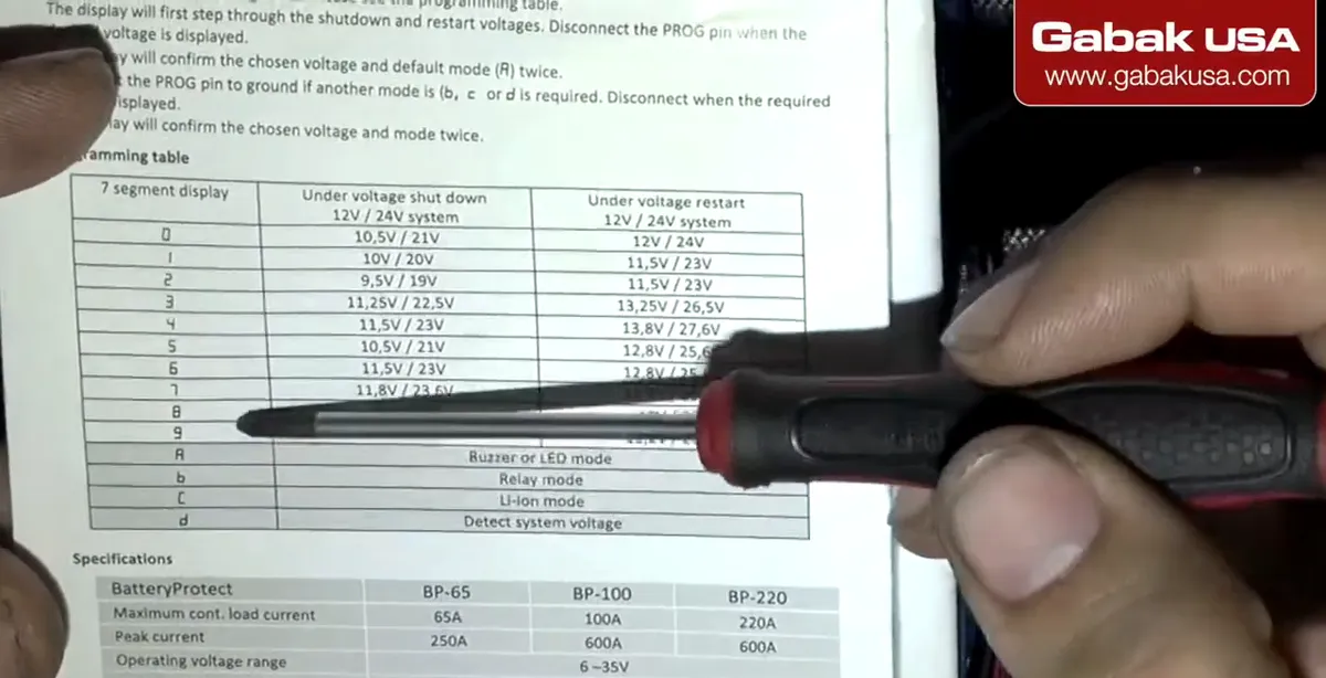
- Start with the manual. The programming table lists the numbers 0 to 9 (each one is a pair of under-voltage shutdown and restart voltages) and the letters for the operating modes.
- The same 7-segment display that shows the setting also shows error codes: E1 short circuit, E2 over temperature, E3 under voltage and E4 over voltage.
Step 2Understand buzzer/LED mode and relay mode
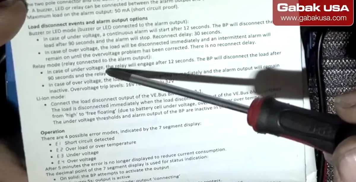
- Mode A (buzzer or LED): on under-voltage a continuous alarm starts after 12 seconds, the load is disconnected after 90 seconds and the alarm stops. The reconnect delay is 30 seconds.
- On over-voltage the manual says the load is disconnected immediately with an intermittent alarm until the problem is corrected.
- Mode b (relay): the relay engages after 12 seconds of under-voltage, and the load is disconnected after 90 seconds. Over-voltage trip levels are 16 V for a 12 V system and 32 V for a 24 V system.
Step 3Choose the shutdown and restart level (level 8)
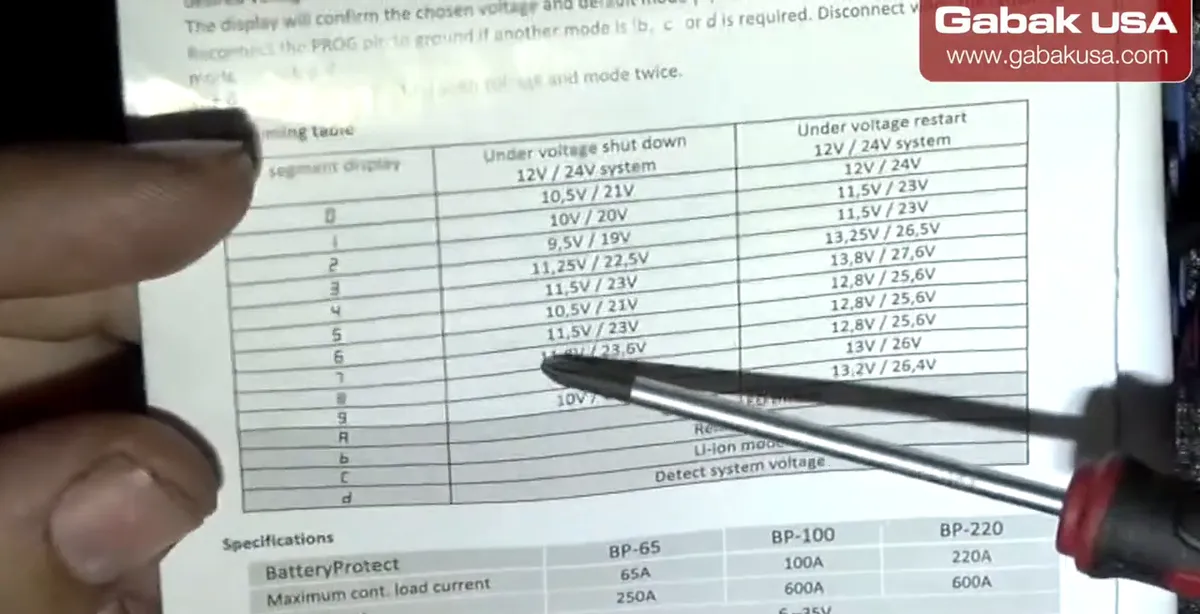
- Each level is a pair: the voltage where the loads are disconnected and the voltage where they are reconnected.
- As the video says, most people recommend level 8: shutdown at 12.0 V and restart at 13.0 V (24.0 V / 26.0 V on a 24 V system).
- Pick the level for your battery type; the full table is below in this article.
Step 4Identify the terminals on the BP-220
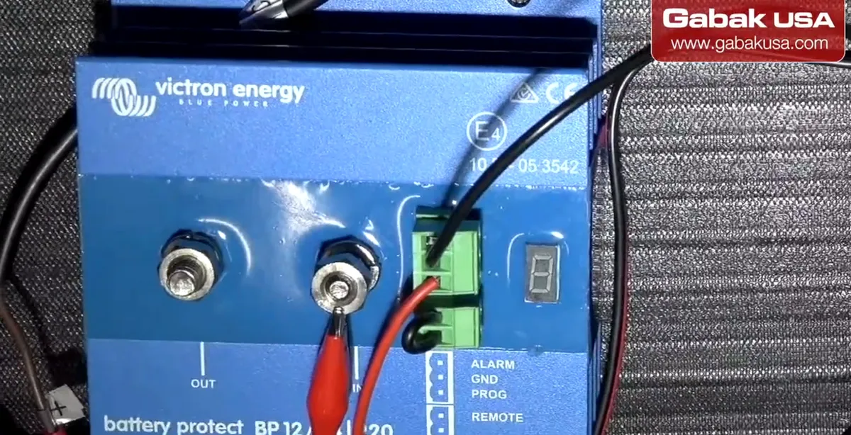
- The unit in the video is a BatteryProtect BP-220 (12/24 V, 220 A). It has two large studs, IN (battery) and OUT (load), and a small terminal block.
- The small pins are ALARM, GND, PROG and the two-pin REMOTE connector.
Step 5Connect battery positive to IN
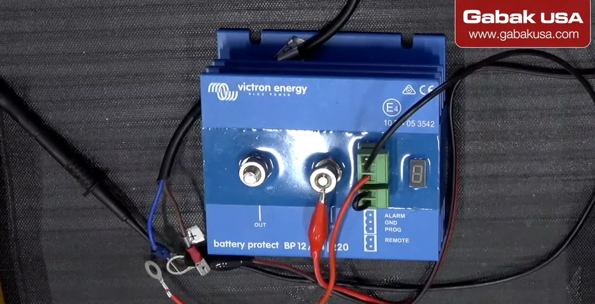
- In the video a bench power supply plays the role of the battery, so the voltage can be raised and lowered for testing.
- Positive goes to IN; negative goes to the negative side of the system (and to GND, Step 9).
- The supply is set to about 12.9 V to start, like a healthy 12 V battery.
Caution: In a real install, Victron requires a properly sized fuse in the cable between the battery and the BatteryProtect, and recommends mounting the unit close to the battery (max 50 cm) in a ventilated spot, but not above the battery.
Step 6Connect OUT to the load
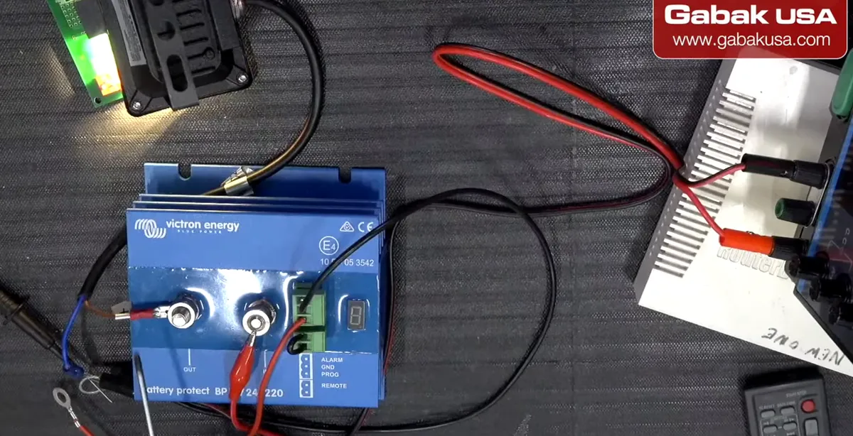
- OUT goes to one side of whatever you want to power; here it is an LED light used as a test load.
- Current only flows from IN to OUT. Never connect it the other way, and never feed current back into OUT.
Caution: Victron's manual says not to connect the load to OUT until the unit is fully programmed. In the video the light is already connected; if you follow the manual, program first (Step 10-11) and connect OUT last.
Step 7Wire the alarm output (optional)
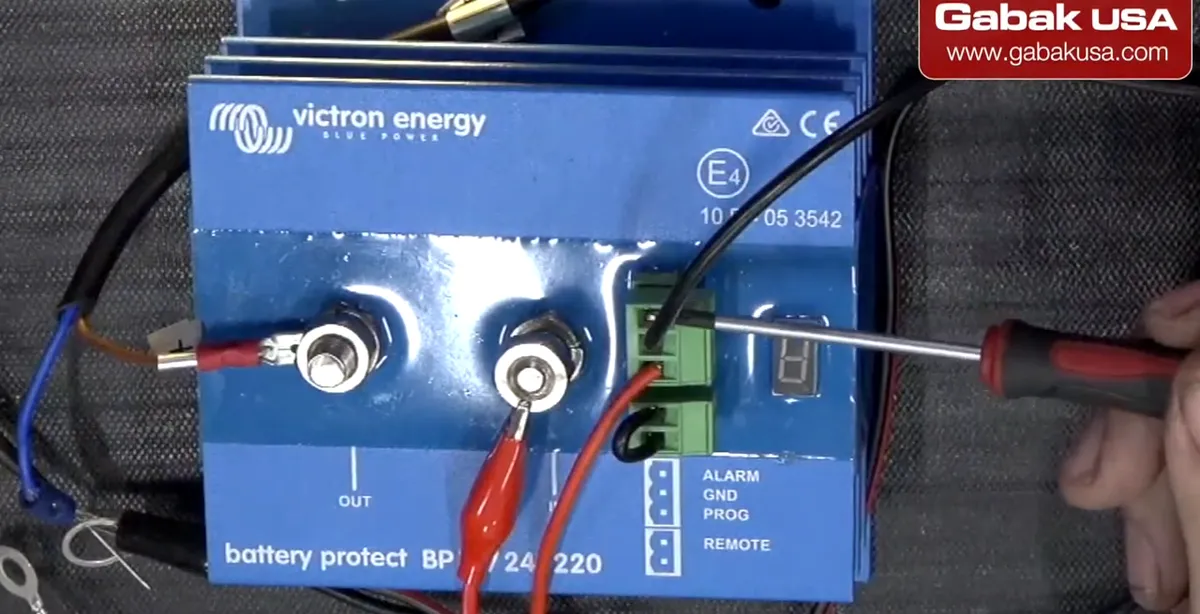
- The ALARM pin is where you connect a buzzer (a speaker, as the video says), an LED or a relay.
- Per the manual, the buzzer, LED or relay goes between the alarm output and battery positive, and the alarm output can handle a maximum of 50 mA.
Step 8Use the REMOTE terminal as an on/off switch
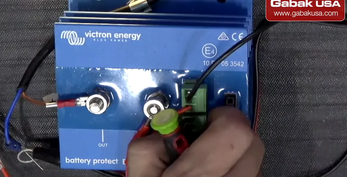
- The two-pin REMOTE connector works like a switch. With the factory wire loop in place, the BatteryProtect can turn on the load.
- If you unplug it, or put an open switch there, there is no load: nothing works.
Step 9Connect GND to battery negative
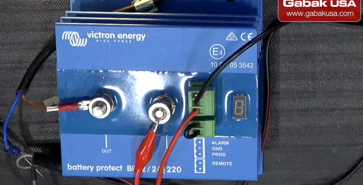
- The GND pin has to go to the negative; in the video the cable runs all the way to the negative of the supply.
- Victron says to use the supplied 1.5 mm² wire, connected directly to the battery negative, with nothing else on that wire (a 300 mA fuse is enough for it).
Step 10Start programming: remove the loop and bridge PROG to GND
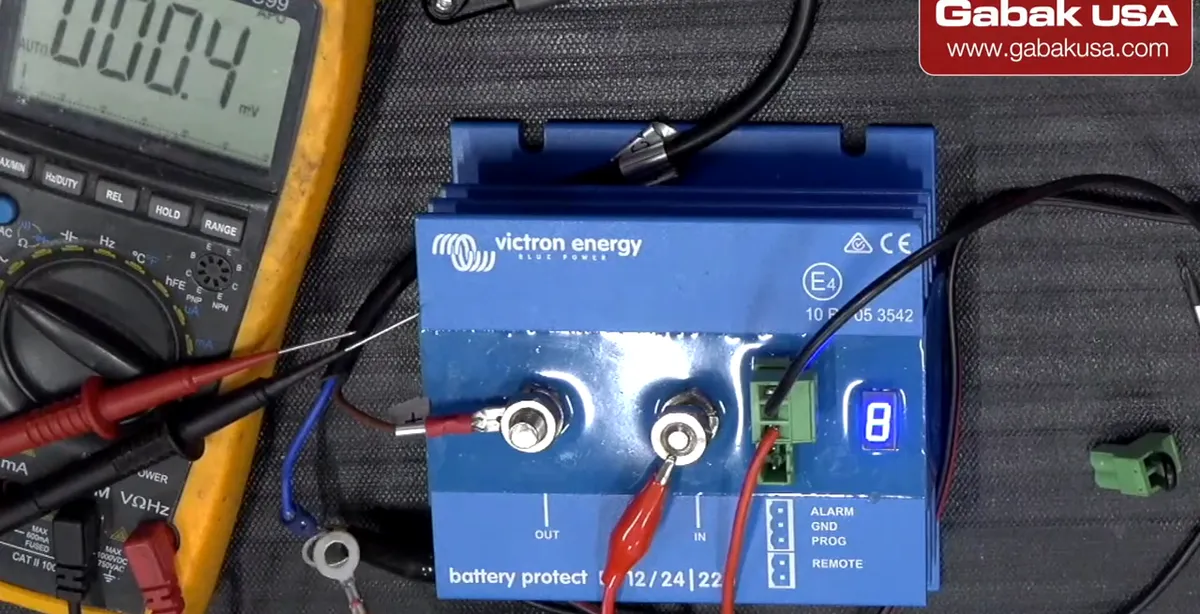
- First unplug the remote loop (the manual lists this as a requirement before programming).
- Then touch the PROG pin to GND (a short wire, the tip of a tool or a push button). The display shows the current setting, for example A 8.
- Keep the connection and the display steps through the numbers 0-9. Release when your level appears; in the video it is left on 8.
Note: Gabriel's opinion: touching pins is not convenient. He would prefer DIP switches or Bluetooth. Victron does sell a Smart BatteryProtect that is set up from the VictronConnect app over Bluetooth; the regular BatteryProtect is programmed only with the PROG pin.
Step 11Select the mode (A, b, C or d)
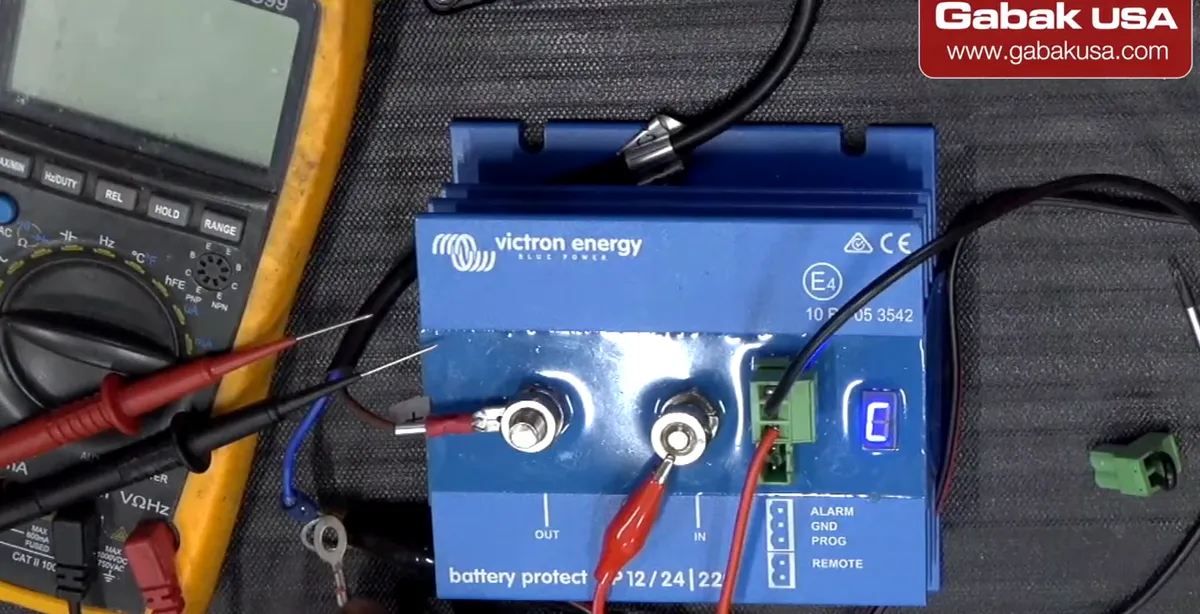
- After the level, the display confirms it with the default mode A. Bridge PROG to GND again to step through A, b, C, d.
- Stop touching when the mode you want is shown; in the video it is left on b. The display confirms the level and mode.
- C (Li-ion) is only for lithium batteries with a BMS that has a load/charge disconnect output. d re-detects the system voltage (12 or 24 V).
- Plug the remote loop back in when you are done so the load can turn on.
Step 12Test the low-voltage cutoff
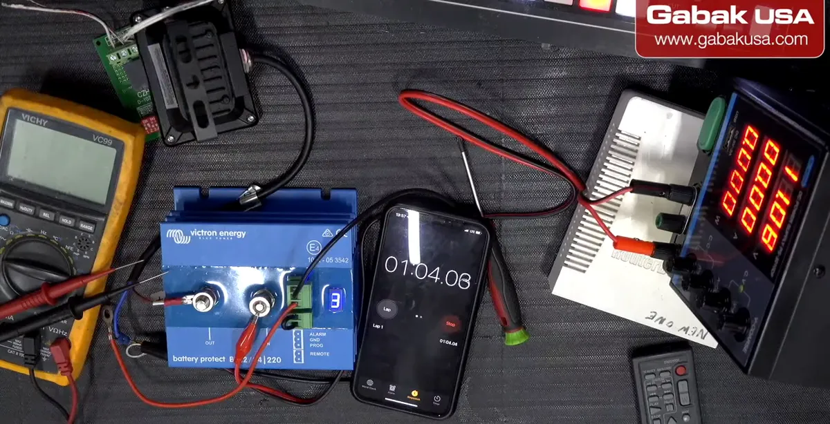
- Pretend the battery is going low: lower the supply to about 11 V, below the 12.0 V shutdown of level 8.
- Start a stopwatch. The load is not cut instantly: in the video the light turned off by itself after the delay (the manual says 90 seconds).
- This delay is useful: a short voltage dip, like starting an engine, will not shut everything off.
Step 13Test the automatic reconnect
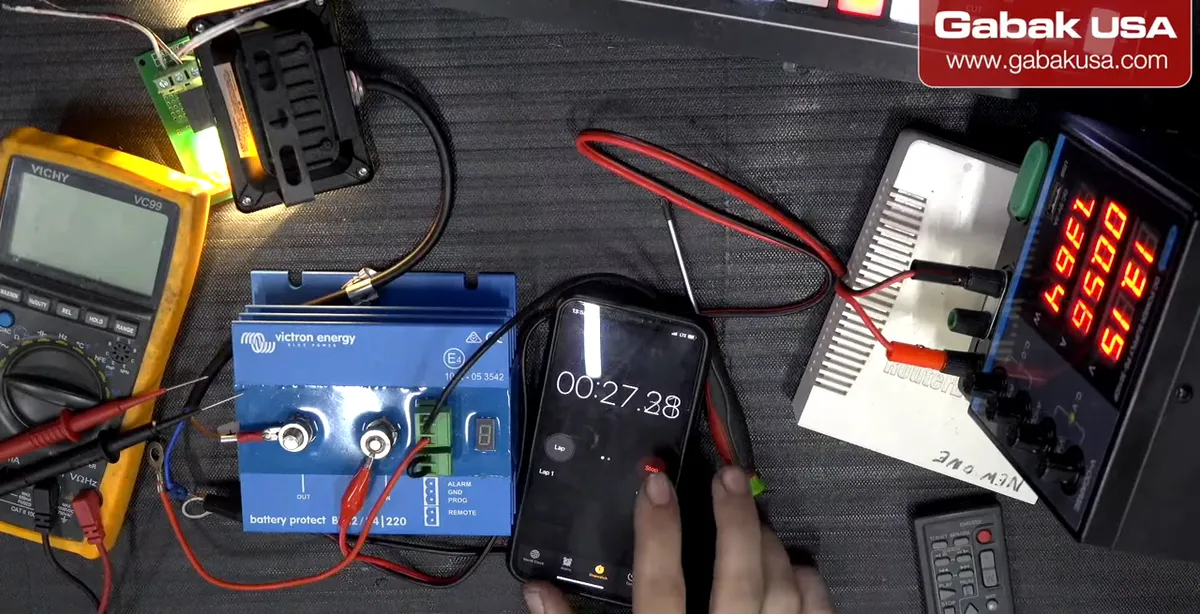
- Now raise the voltage above the 13.0 V restart level; in the video the supply is at 13.16 V.
- Start the stopwatch again. After the reconnect delay the light comes back on.
Step 14Test over-voltage with a multimeter
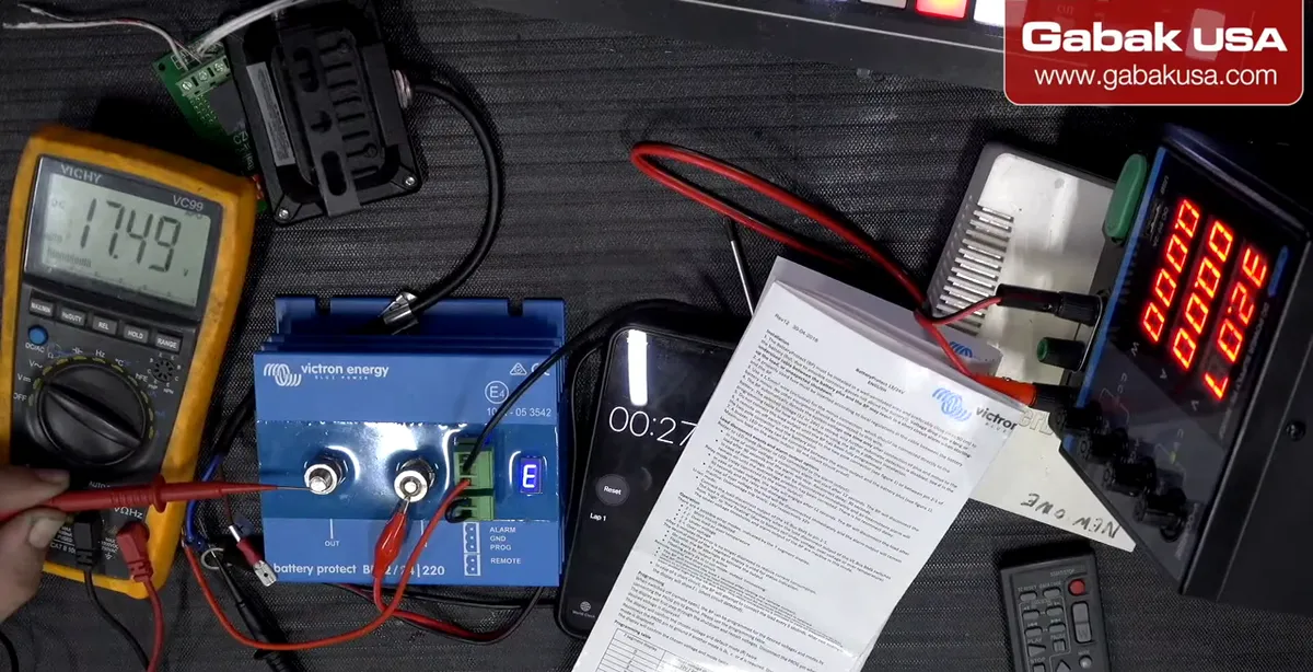
- To protect the LED light, Gabriel unplugs it and uses a multimeter on the output instead. At about 13.2 V the meter reads almost the same as the supply.
- He then raises the supply to 16-17 V, then 21 V and 32 V. The display shows an error, but the meter still reads voltage on the output.
- His result: under-voltage protection works great and never gave him problems, but over-voltage did not disconnect in this test the way the relay-mode table says (16 V for 12 V systems).
Caution: Do not test over-voltage with expensive loads connected. If you rely on over-voltage protection, test it with a cheap load and confirm with the manufacturer.
Note: The video does not explain why. One possibility to check: a digital multimeter on an output with no load connected can show voltage through tiny leakage even when a solid-state switch is off. Repeating the test with a small load connected would give a clearer answer. If you are new to measuring DC voltage, the meter method in how to test any laptop charger works the same way.
What a Victron BatteryProtect does (and why you need one)
Deep discharge is one of the fastest ways to ruin a battery. Victron's own description, quoted in the video description, is simple: the BatteryProtect disconnects the battery from non-essential loads before it is completely discharged (which would damage the battery) or before there is not enough power left to crank the engine.
Unlike a relay, it switches with MOSFETs, so there are no sparks, and it uses very little current itself (1.5 mA when on, per the datasheet). It also has delays built in: the alarm waits 12 seconds and the disconnect waits 90 seconds, so starting an engine or a short surge does not shut everything down. That gives you time to reduce the load or start a charger before the loads are switched off.
Typical uses: fridges, lights, pumps and fans in an RV or van (for example a roof fan like in fixing a Maxxair fan that won't turn on), boat house batteries, and small solar systems.
The BP-65, BP-100 and BP-220 are programmed the same way; they differ in maximum continuous current (65 A, 100 A and 220 A). For AC backup power in a home or office instead of a DC battery bank, a UPS is the simpler tool; see the CyberPower ST425 UPS review and setup.
BatteryProtect programming table (12 V and 24 V)
From Victron's BatteryProtect 12/24V manual:
| Display | Shutdown 12 V / 24 V | Restart 12 V / 24 V |
|---|---|---|
| 0 | 10.5 V / 21.0 V | 12.0 V / 24.0 V |
| 1 | 10.0 V / 20.0 V | 11.5 V / 23.0 V |
| 2 | 9.5 V / 19.0 V | 11.5 V / 23.0 V |
| 3 | 11.25 V / 22.5 V | 13.25 V / 26.5 V |
| 4 | 11.5 V / 23.0 V | 13.8 V / 27.6 V |
| 5 | 10.5 V / 21.0 V | 12.8 V / 25.6 V |
| 6 | 11.5 V / 23.0 V | 12.8 V / 25.6 V |
| 7 | 11.8 V / 23.6 V | 12.8 V / 25.6 V |
| 8 | 12.0 V / 24.0 V | 13.0 V / 26.0 V |
| 9 | 10.0 V / 20.0 V | 13.2 V / 26.4 V |
| A | Buzzer or LED mode | |
| b | Relay mode | |
| C | Lithium (Li-ion) mode | |
| d | Detect system voltage |
The factory default is level 0 (10.5 V off, 12 V on) in mode A. Level 8, used in the video, is more conservative: it stops at 12.0 V, which leaves more charge in the battery.
Wiring rules from the Victron manual
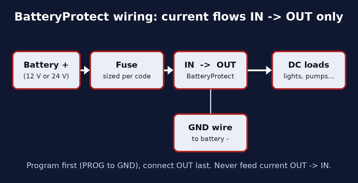
- Current flows IN to OUT only. The BatteryProtect is uni-directional. It can switch a load *or* a charger, but not both at once, and reverse current from OUT to IN damages it. To use it on a charger, the charger connects to IN.
- Never connect an inverter or inverter/charger DC input to it. Their input capacitors trigger the short-circuit protection (E1), and reverse current can damage the unit. Use the BatteryProtect to drive the inverter's remote on/off port instead.
- Fuse the cable between battery and BatteryProtect, and size cables for the load. Voltage drop on a thin or long cable can cause false short-circuit alarms or unexpected shutdowns.
- GND to battery negative with the supplied thin wire, nothing else on it.
- Program before connecting OUT, with the remote loop removed.
- The unit detects 12 or 24 V only once, at first power-up. If you move it to a different system, use mode d to re-detect.
Caution: work on battery systems with the battery disconnected or fused, and remove rings and watches. A short across a battery can melt tools and cables.
BatteryProtect error codes and troubleshooting
| Display | Meaning | What to check |
|---|---|---|
| E1 | Short circuit | Short in the load wiring, load above the rating, high inrush (inverters), loose or thin cables |
| E2 / P2 | Over temperature / warning | Load current too high, bad connections, unit in a hot spot |
| E3 / P3 | Under voltage / warning | Battery low for 90 s: switch off loads and recharge; check the charging system |
| E4 | Over voltage | Above 16 V (12 V system) or 32 V (24 V): check charger settings and the system voltage the BP detected |
| Nothing turns on | Remote loop missing or switch open | Plug the loop back in or close the remote switch |
| Won't program | OUT connected or loop still in | Follow the requirements: IN + GND connected, OUT not connected, loop removed |
After 5 minutes the error is no longer shown on the display, to save power. If the load won't come back after a low-voltage cutoff, remember it needs the battery above the restart voltage, not just above the shutdown voltage.
Frequently asked questions
How do you program a Victron BatteryProtect?
Connect battery positive to IN and GND to negative, remove the remote loop, and bridge PROG to GND. The display steps through levels 0-9; release on the one you want, then bridge again to choose mode A, b, C or d.
What is the best setting for a Victron BatteryProtect?
Many people use level 8, which disconnects at 12.0 V and reconnects at 13.0 V on a 12 V system. Choose based on your battery type and how much charge you want to keep.
How long does the BatteryProtect wait before disconnecting?
The alarm starts after 12 seconds of low voltage and the load is disconnected after 90 seconds. In the video the light turned off by itself after the delay.
What is the difference between mode A and mode b?
Mode A drives a buzzer or LED on the alarm output; mode b is for a relay. Both disconnect the load after 90 seconds of under-voltage.
Does the BatteryProtect protect against over-voltage?
The manual says it disconnects the load above about 16 V (12 V system) or 32 V (24 V). In the video the display showed an error, but the multimeter still read voltage on the output, so test it yourself before relying on it.
Can I connect an inverter to a Victron BatteryProtect?
Not on its DC input. Victron forbids it because of reverse current and inrush; use the BatteryProtect to control the inverter's remote on/off port instead.
Can a BatteryProtect be used with lithium batteries?
Yes. Use mode C only if your BMS has a load or charge disconnect output wired to REMOTE; for drop-in batteries without that output, use mode A or b.
Watch the video




Comments
Comments appear after Gabriel reviews them.
Loading comments…